

Flex Circuit PCBs
Compared to rigid PCBs and wire harnesses, flex circuits are more reliable due to their flexible nature. They can bend and flex to fit the space in which they are being used and are better at absorbing vibrations, protecting the components from damage. This translates into less wear and tear, more reliability, and lower costs for the end customer.
When designing a flex circuit pcb, it is important to consider the materials and construction process used. For example, choosing a conductive material with a low coefficient of expansion (CCE) and a good thermal conductivity is key to reducing stress on the copper layers and maintaining high signal integrity. The thickness of the copper layer is also important as it affects flexing performance. Thicker layers are stiffer and have a higher CTE, making them less flexible. It is best to choose a thinner layer of copper for more flexibility.
It is also helpful to use a manufacturing process that minimizes copper deformation during etching, and ensures that the drill-to-copper distance is large enough. This will help to prevent cracking of vias during thermal cycling, a common issue that occurs when the resin and copper have different CTE values.
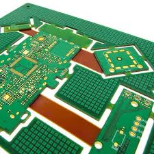
Reliability of Flex Circuit PCBs
In addition, the use of a panel plating technique that deposits copper only on pads and vias rather than over the entire board (button plating) can reduce copper flexing and improve etch yields in small traces. This is especially beneficial in flex-to-flex designs where a smaller copper layer and more controlled impedance are required.
A flex circuit’s reliability depends on its thickness, copper width and spacing, the number of layers, and the size of its bend radius. The smallest bend radius possible is usually between 1 mm and 5 mm. If the design requires a larger radius, it may be necessary to increase the layer count, add mechanical reinforcements, or add a thin section of PSA in the fold area.
Lastly, when assembling a flex circuit PCB, it is critical to pay attention to the tolerances of the components and ensure that all solder joints have proper depth and alignment. This will help to prevent premature failure from improperly seated components or misaligned solder connections. It is recommended to use a smart assembly machine that can recognize the dimensional variations of a flex stack-up and place the components correctly.
A flex PCB should also be tested after production to ensure that the circuit works as expected, and that there are no electrical issues. PCBWay offers a variety of testing options, including electrical and environmental testing, to ensure that your flex circuit is functional and will perform well in the intended application.
The final step in ensuring the quality of a flex PCB is to ensure that it meets IPC standards for the materials and layout of the traces, tracks and other features on the board. Detailed fabrication drawings should be created to clearly illustrate the layer arrangement, coverlay, and adhesives used in the board.