

RF circuit boards support antenna matching
Antenna matching is a critical aspect of ensuring efficient wireless communication, as it directly impacts the performance of any RF (Radio Frequency) system. The process of antenna matching involves adjusting the impedance of the antenna to match the impedance of the RF circuit board or the transmitter/receiver to minimize signal reflections and maximize power transfer. In RF systems, impedance mismatches can lead to signal loss, reduced range, and interference, which can compromise the overall performance of the system. RF circuit boards play a crucial role in supporting antenna matching by providing the necessary components and design strategies to ensure that the antenna impedance is properly matched to the rest of the system.
The first role of RF circuit boards in antenna matching is related to their ability to control impedance. Impedance matching is essential for the optimal transfer of RF signals between the circuit board and the antenna. The impedance of a typical antenna is often 50 ohms, but RF circuit boards may have different characteristic impedances based on their design and the materials used. To achieve antenna matching, the circuit board is designed to ensure that the signal transmitted or received by the antenna is not reflected back into the system. This is achieved by carefully controlling the trace widths and distances between signal paths on the circuit board, making sure that the impedance of the signal path matches the antenna’s impedance.
One of the key elements that support antenna matching on an RF circuit board is the use of microstrip lines or coplanar waveguides. These are types of transmission lines that are commonly used in RF circuit boards to route high-frequency signals. Microstrip lines are designed with a controlled impedance, typically 50 ohms, to ensure that the signal travels through the board with minimal reflection. When connecting the antenna to the circuit board, the microstrip line ensures that the transition from the antenna to the circuit board maintains the required impedance, avoiding mismatches that would lead to power loss. The design of the microstrip line, including the width of the traces and the distance to the ground plane, is carefully optimized to match the antenna impedance and reduce signal reflections.
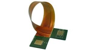
How do RF circuit boards support antenna matching?
Another important design feature of rf circuit board that supports antenna matching is the use of impedance matching networks. These networks are composed of passive components such as inductors, capacitors, and resistors, which are strategically placed on the circuit board to adjust the impedance seen by the antenna. The matching network compensates for any impedance mismatch between the antenna and the circuit board, allowing for efficient power transfer. There are different types of matching networks, such as L-networks, T-networks, and Pi-networks, each offering a specific way to achieve impedance matching depending on the application. By using these matching networks, RF circuit boards can ensure that the antenna operates efficiently across a wide range of frequencies.
In some cases, RF circuit boards also incorporate tunable components to dynamically adjust the impedance of the antenna system. These components, such as varactors (voltage-variable capacitors), allow the impedance to be adjusted in real-time, which can be useful in applications where the frequency or operating conditions change. This tunability can help compensate for variations in environmental conditions, such as temperature or humidity, which may otherwise affect the impedance matching and signal strength. By integrating these tunable components into the circuit board, the system can maintain optimal antenna matching and signal quality over time.
Moreover, advanced techniques like embedded passive components and optimization of the antenna design itself are also employed to support better antenna matching. For example, RF circuit boards can be designed with integrated antennas, where the circuit board and antenna are fabricated together as a single unit. This integration reduces the chances of mismatch and ensures that the impedance is consistently matched across the entire system. Additionally, by optimizing the layout and minimizing losses due to signal reflections, the efficiency of the antenna is maximized, which is particularly important in applications such as mobile communications, IoT (Internet of Things) devices, and wireless sensor networks.